

- Industry > Automotive
- Application > Machine Tending
- Sector > Manufacturing
- #AutomatedHandling
- #DoosanTW2600M
- #FactoryProductivity
- #FANUC MerchineTending
- #FANUCRobot
- #GantryRobot
- #LinearTrack
- #MachineTending
- #TurningCenterAutomation

Process Overview
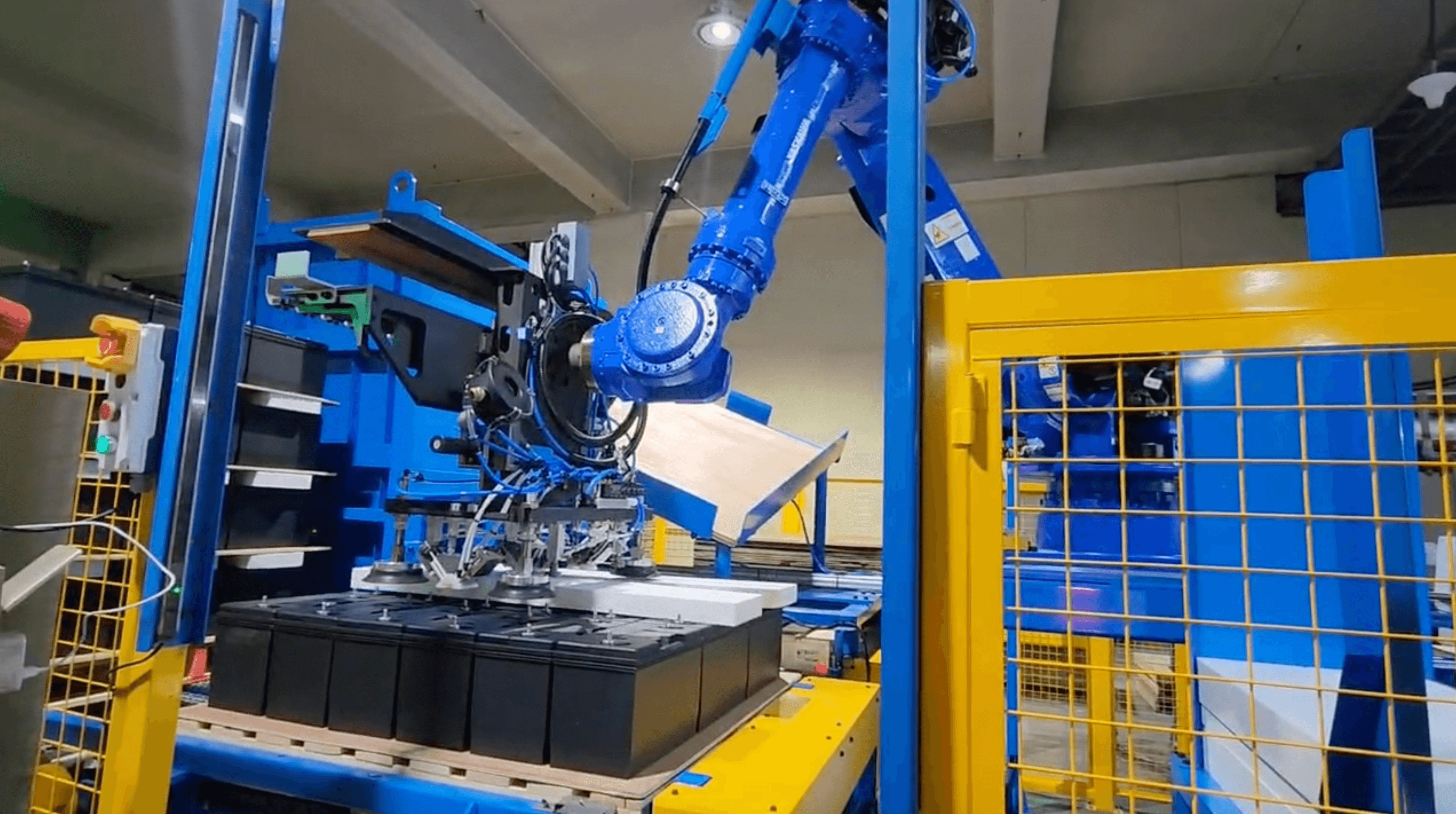
BIGWAVE ROBOTICS developed a robotic machine tending system for automotive differential case machining using FANUC M-20iA/35M robots and Doosan TW2600M turning centers. The system automates part loading, CNC machining, transfer between processes, and unloading in a continuous workflow.
The FANUC robots are installed on overhead linear tracks above the machine tools, efficiently utilizing floor space while keeping the front side of the turning centers clear for tool changes and maintenance.
The system integrates part reorientation, gantry transfer, and post-machining processes, reducing manual handling of heavy differential cases. This minimizes idle time, improves productivity, and reduces operator workload.
Components
- Robot
FANUC M-20iA/35M x 2 units
6-axis articulated robot
Payload: 35 kg
Working range: 1,813 mm
Weight: 252 kg
Repeatability: ±0.03 mm
IP rating: IP67 (arm), IP54 (body)
Robot-mounted axis: 7-axis
- Peripherals
Tool: pneumatic double gripper x 2 units
Equipment: Doosan Turning Center TW2600M x 6 units (OP10 x 3 units, OP20 x 3 units)
Peripheral devices: mobile robot base (linear track), TRG (Top Robot Gantry) series by Youngchang Robotech
OP10: workpiece infeed lift feeder, workpiece gripping correction jig x 3 sets, 1st machining completed jig
OP10–OP20 transfer: gantry robot for inter-process transfer (3-axis)
OP20: infeed waiting jig, air blowing unit
Outfeed: gantry robot for discharge (2-axis), discharge jig
Safety fence
Workflow
- STEP 1.
- Picking the Differential Case — A FANUC robot picks a differential case from the lift feeder for automated machining.
- STEP 2.
- First Turning Operation — The FANUC robot loads the differential case into the turning center for the first CNC machining operation.
- STEP 3.
- Part Alignment & Transfer Setup — The partially machined differential case is positioned and aligned at a buffer station for the next operation.
- STEP 4.
- Part Turnover & Gantry Transfer — The differential case is turned over and transferred by a gantry system for the next machining operation.
- STEP 5.
- Second Turning Operation — The reoriented differential case is loaded into the turning center for the second CNC machining operation.
- STEP 6.
- Air Blowing after Machining — Air blowing removes residual coolant and chips from the machined differential case.
- STEP 7.
- Finished Part Unloading — The finished differential case is transferred to the discharge station for unloading.
※ The content provided by Bigwave Robotics is protected under U.S. and Canadian copyright and intellectual property laws. Unauthorized reproduction, distribution, or use of this content is strictly prohibited.